Building a Procedural Maze Generator in UE5 Blueprints — Part 3
Introduction
In Part 2, you built the full maze generation logic.
Your system can now:
- generate a complete maze in memory
- track visited cells
- remove walls between cells
- backtrack correctly using a stack
But right now, nothing is visible.
In this part, we will fix that.
What You Will Build in This Part
By the end of Part 3, your system will:
- render the maze using floor and wall meshes
- place walls based on cell data
- create one entrance and one exit
- fully generate the maze in the editor using the Construction Script
Before You Start
You should already have from Part 2:
InitializeGridGetUnvisitedNeighborsRemoveWallBetweenGenerateMaze
You should also already have these variables:
MazeGridMazeWidthMazeHeightCellSizeMazeSeedRandomStream
You should also have these HISM components:
FloorHISMWallHISM
Step 1 — Create the BuildMazeVisuals Function
What this step does
This function turns your invisible maze data into visible floor and wall meshes.
It loops through every cell in MazeGrid and:
- places one floor tile per cell
- places wall meshes wherever a wall boolean is still
True
Before you start
Make sure both HISM components have a mesh assigned from Part 1. If either is empty, go back to Step 1.3 of Part 1 before continuing.
Also review the wall offset reference table below before building this function. You will refer back to it throughout this step.
Wall offset and rotation reference
| Wall | X offset | Y offset | Z offset | Rotation Z |
|---|---|---|---|---|
| North | 0 | -CellSize/2 | CellSize/2 | 0° |
| East | CellSize/2 | 0 | CellSize/2 | 90° |
| South | 0 | CellSize/2 | CellSize/2 | 180° |
| West | -CellSize/2 | 0 | CellSize/2 | -90° |
Z offset places the wall centre at half the cell height so it sits correctly above the floor tile. Rotation only matters if you replace the Cube mesh with a custom asymmetric wall mesh later.
Mesh scale reference
The built-in Cube mesh is 100×100×100 units. Since CellSize is 200 by default, you must scale the meshes to fill the cell correctly.
| Mesh | Scale X | Scale Y | Scale Z |
|---|---|---|---|
| Floor | CellSize / 100 | CellSize / 100 | 0.1 |
| Wall | CellSize / 100 | 0.1 | CellSize / 100 |
If you change
CellSizelater, the scale calculations update automatically because they read directly from the variable.
Instructions
Step 1.1 — Create the function
-
In the My Blueprint panel, find Functions
-
Click the + button next to Functions
-
Name the function:
BuildMazeVisuals -
Press Enter
Step 1.2 — Add comment boxes
Before placing any nodes, set up comment boxes to keep the graph organised.
Step 1.2.1 — Add the comment boxes
-
Left-click and drag in empty graph space to select an area
-
Press C
-
Name the comment box:
Floor -
Repeat this process four more times and name them:
North WallEast WallSouth WallWest Wall
Arrange them left to right or top to bottom — whichever feels clearer to you.
Step 1.3 — Add a For Loop
The For Loop goes through every cell in MazeGrid. Each pass places one floor tile and checks all four walls.
Step 1.3.1 — Place the For Loop
-
Right-click in empty graph space
-
Search for:
For Loop -
Choose the plain:
For Loop -
Connect the white execution pin from:
BuildMazeVisuals(function entry node)to
For Loop
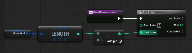
Step 1.3.2 — Set the loop range
-
Drag
MazeGridinto the graph as Get -
Drag from the
MazeGridpin -
Search for:
Length -
Click:
Array Length -
Drag from the
Lengthresult -
Search for:
- -
Choose:
Subtract -
Set the second input to:
1 - Connect:
- subtraction result →
For Loop.Last Index
- subtraction result →
- Set:
For Loop.First Index = 0
Arrays start at 0. If
MazeGridhas 144 cells (12×12), the last valid index is 143 — not 144. That is why we subtract 1.
Step 1.4 — Get the current cell
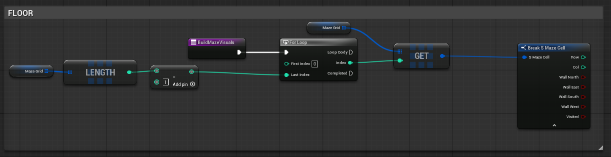
Each loop pass gives us an index. We use that index to read the matching cell from MazeGrid and access its data.
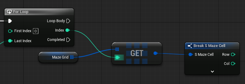
Step 1.4.1 — Read the cell from MazeGrid
-
Drag
MazeGridinto the graph as Get -
Drag from the
MazeGridpin -
Search for:
Get (a copy) -
Click:
Get (a copy) -
Drag
For Loop.Indexand connect:For Loop.Index→ Index onGet (a copy)
Step 1.4.2 — Break the cell struct
-
Drag from the output of
Get (a copy) -
Search for:
Break S_MazeCell -
Click:
Break S_MazeCell
This gives you access to:
RowColbWallNorthbWallEastbWallSouthbWallWest
You will reuse the output pins of this Break node throughout the rest of the function. Place it in a central position and do not create additional Break nodes for the same cell.
Step 1.5 — Calculate the cell world location
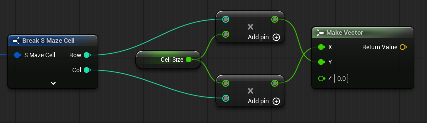
The maze stores cells as rows and columns. Meshes need world positions. This step converts grid coordinates into a world location vector.
Col→ X axisRow→ Y axis- Z stays
0(floor level)
Step 1.5.1 — Calculate X
-
Drag from
Col(onBreak S_MazeCell) -
Search for:
* -
Choose:
Multiply -
Drag
CellSizeinto the graph as Get -
Connect:
CellSize→ second input of*
Step 1.5.2 — Calculate Y
-
Drag from
Row(onBreak S_MazeCell) -
Search for:
* -
Choose:
Multiplyr -
Drag
CellSizeinto the graph as Get (you can use the same CellSize from the last step as well) -
Connect:
CellSize→ second input of*
Step 1.5.3 — Make the cell location vector
-
Right-click in empty graph space
-
Search for:
Make Vector -
Click:
Make Vector - Connect:
Col × CellSizeresult →Make Vector.XRow × CellSizeresult →Make Vector.Y
- Set:
Make Vector.Z = 0
This vector is the centre point of the current cell. All floor and wall placements will use this as their base position.
Step 1.6 — Calculate the floor mesh scale
The Cube mesh is 100×100×100 units. You must scale it to fill the cell.
Step 1.6.1 — Calculate scale XY
-
Drag
CellSizeinto the graph as Get -
Drag from the
CellSizepin -
Search for:
/ -
Choose:
Divide -
Set the second input to:
100
This gives CellSize / 100.
Step 1.6.2 — Make the floor scale vector
-
Right-click in empty graph space
-
Search for:
Make Vector -
Click:
Make Vector -
Connect:
CellSize / 100→Make Vector.XCellSize / 100→Make Vector.Y
You can drag multiple wires from the same output pin — just drag from it again.
- Set:
Make Vector.Z = 0.1
Z scale of 0.1 makes the floor tile thin. You can adjust this later.
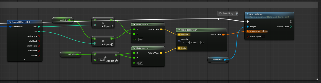
Step 1.7 — Add the floor mesh
Place all nodes for this section inside the Floor comment box.
Step 1.7.1 — Create the floor transform
-
Right-click in empty graph space
-
Search for:
Make Transform -
Click:
Make Transform - Connect:
- cell location
Make Vectoroutput →Make Transform.Location - floor scale
Make Vectoroutput →Make Transform.Scale
- cell location
- Set Rotation:
- X =
0 - Y =
0 - Z =
0
- X =
Step 1.7.2 — Add the floor instance
-
Drag
FloorHISMinto the graph as Get -
Drag from the
FloorHISMpin -
Search for:
Add Instance -
Click:
Add Instance -
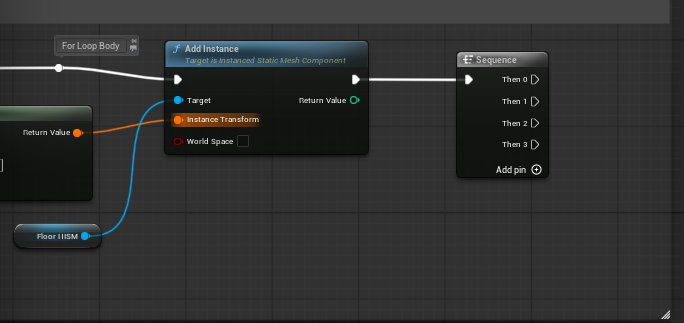
Connect:
For Loop.Loop Body→FloorHISM Add Instance- floor
Make Transform→Add Instance.Instance Transform
Step 1.8 — Add the Sequence node
The Sequence node lets all four wall checks run independently after the floor is placed.
Because we are using a Sequence node, each wall check runs on its own execution path. The
Branch.Falsepins do not need to connect anywhere — if the wall does not exist, that branch simply ends and the Sequence continues to the next direction.
Step 1.8.1 — Place and connect the Sequence node
-
Right-click in empty graph space
-
Search for:
Sequence -
Click:
Sequence -
Connect the white execution pin from:
FloorHISM Add Instanceto
Sequence
The Sequence node starts with two outputs. Add two more:
- Click Add pin + on the Sequence node twice
You should now have:
Then 0→ North wall checkThen 1→ East wall checkThen 2→ South wall checkThen 3→ West wall check
Step 1.9 — Calculate the wall mesh scale
All four walls use the same scale. Build it once and reuse the output.
Step 1.9.1 — Calculate wall scale
-
Drag
CellSizeinto the graph as Get -
Drag from the
CellSizepin -
Search for:
/ -
Choose:
Divide -
Set the second input to:
100
This gives CellSize / 100.
Step 1.9.2 — Make the wall scale vector
-
Right-click in empty graph space
-
Search for:
Make Vector -
Click:
Make Vector - Connect:
CellSize / 100→Make Vector.X
- Set:
Make Vector.Y = 0.1Make Vector.Z→ connectCellSize / 100here as well
You can drag a second wire from the same
CellSize / 100output pin.
Y scale of 0.1 gives the wall its thickness. X and Z scale to match the cell size so the wall fills the full cell width and height.

Step 1.10 — Add the North wall
Place all nodes for this section inside the North Wall comment box.
Step 1.10.1 — Add the North Branch
-
Right-click in empty graph space
-
Search for:
Branch -
Click:
Branch -
Connect the white execution pin from:
Sequence.Then 0to
Branch(North) -
Connect:
bWallNorth(fromBreak S_MazeCell) →Branch.Condition
Step 1.10.2 — Calculate the North wall offset
The North wall sits at:
- X =
0 - Y =
-CellSize / 2 - Z =
CellSize / 2
-
Drag
CellSizeinto the graph as Get -
Drag from the
CellSizepin -
Search for:
/ -
Choose:
Divide -
Set the second input to:
2
This gives CellSize / 2.
-
Right-click in empty graph space
-
Search for:
Make Vector -
Click:
Make Vector - Connect:
CellSize / 2→Make Vector.Z
- Set:
Make Vector.X = 0
-
Drag from the
CellSize / 2result again -
Search for:
* -
Choose:
Multiply -
Set the second input to:
-1 - Connect:
- output of the
Multiplynode →Make Vector.Y
- output of the
Step 1.10.3 — Add the offset to the cell location
-
Drag from the cell location
Make Vectoroutput (from Step 1.5.3) -
Search for:
+ -
Choose:
Add -
Connect:
- North wall offset
Make Vector→ second input of+
- North wall offset
Step 1.10.4 — Create the North wall transform
-
Right-click in empty graph space
-
Search for:
Make Transform -
Click:
Make Transform - Connect:
+result →Make Transform.Location- wall scale
Make Vectoroutput (from Step 1.9.2) →Make Transform.Scale
- Set Rotation:
- X =
0 - Y =
0 - Z =
0
- X =
Step 1.10.5 — Add the North wall instance
-
Drag
WallHISMinto the graph as Get -
Drag from the
WallHISMpin -
Search for:
Add Instance -
Click:
Add Instance -
Connect the white execution pin from:
Branch.True(North)to
WallHISM Add Instance -
Connect:
- North wall
Make Transform→Add Instance.Instance Transform
- North wall
Leave
Branch.Falseunconnected. The Sequence node handles continuation.

Step 1.11 — Add the East wall
Place all nodes for this section inside the East Wall comment box.
Step 1.11.1 — Add the East Branch
-
Right-click in empty graph space
-
Search for:
Branch -
Click:
Branch -
Connect the white execution pin from:
Sequence.Then 1to
Branch(East) -
Connect:
bWallEast(fromBreak S_MazeCell) →Branch.Condition
Step 1.11.2 — Calculate the East wall offset
The East wall sits at:
- X =
CellSize / 2 - Y =
0 - Z =
CellSize / 2
-
Drag
CellSizeinto the graph as Get -
Drag from the
CellSizepin -
Search for:
/ -
Choose:
Float / Float -
Set the second input to:
2
This gives CellSize / 2.
-
Right-click in empty graph space
-
Search for:
Make Vector -
Click:
Make Vector -
Connect:
CellSize / 2→Make Vector.XCellSize / 2→Make Vector.Z
Drag a second wire from the same
CellSize / 2output pin for Z.
- Set:
Make Vector.Y = 0
Step 1.11.3 — Add the offset to the cell location
-
Drag from the cell location
Make Vectoroutput (from Step 1.5.3) -
Search for:
+ -
Choose:
Vector + Vector -
Connect:
- East wall offset
Make Vector→ second input of+
- East wall offset
Step 1.11.4 — Create the East wall transform
-
Right-click in empty graph space
-
Search for:
Make Transform -
Click:
Make Transform - Connect:
+result →Make Transform.Location- wall scale
Make Vectoroutput (from Step 1.9.2) →Make Transform.Scale
- Set Rotation:
- X =
0 - Y =
0 - Z =
90
- X =
Step 1.11.5 — Add the East wall instance
-
Drag
WallHISMinto the graph as Get -
Drag from the
WallHISMpin -
Search for:
Add Instance -
Click:
Add Instance -
Connect the white execution pin from:
Branch.True(East)to
WallHISM Add Instance -
Connect:
- East wall
Make Transform→Add Instance.Instance Transform
- East wall
Leave
Branch.Falseunconnected.

Step 1.12 — Add the South wall
Place all nodes for this section inside the South Wall comment box.
Step 1.12.1 — Add the South Branch
-
Right-click in empty graph space
-
Search for:
Branch -
Click:
Branch -
Connect the white execution pin from:
Sequence.Then 2to
Branch(South) -
Connect:
bWallSouth(fromBreak S_MazeCell) →Branch.Condition
Step 1.12.2 — Calculate the South wall offset
The South wall sits at:
- X =
0 - Y =
CellSize / 2 - Z =
CellSize / 2
-
Drag
CellSizeinto the graph as Get -
Drag from the
CellSizepin -
Search for:
/ -
Choose:
Float / Float -
Set the second input to:
2
This gives CellSize / 2.
-
Right-click in empty graph space
-
Search for:
Make Vector -
Click:
Make Vector -
Connect:
CellSize / 2→Make Vector.YCellSize / 2→Make Vector.Z
Drag a second wire from the same
CellSize / 2output pin for Z.
- Set:
Make Vector.X = 0
Step 1.12.3 — Add the offset to the cell location
-
Drag from the cell location
Make Vectoroutput (from Step 1.5.3) -
Search for:
+ -
Choose:
Vector + Vector -
Connect:
- South wall offset
Make Vector→ second input of+
- South wall offset
Step 1.12.4 — Create the South wall transform
-
Right-click in empty graph space
-
Search for:
Make Transform -
Click:
Make Transform - Connect:
+result →Make Transform.Location- wall scale
Make Vectoroutput (from Step 1.9.2) →Make Transform.Scale
- Set Rotation:
- X =
0 - Y =
0 - Z =
180
- X =
Step 1.12.5 — Add the South wall instance
-
Drag
WallHISMinto the graph as Get -
Drag from the
WallHISMpin -
Search for:
Add Instance -
Click:
Add Instance -
Connect the white execution pin from:
Branch.True(South)to
WallHISM Add Instance -
Connect:
- South wall
Make Transform→Add Instance.Instance Transform
- South wall
Leave
Branch.Falseunconnected.

Step 1.13 — Add the West wall
Place all nodes for this section inside the West Wall comment box.
Step 1.13.1 — Add the West Branch
-
Right-click in empty graph space
-
Search for:
Branch -
Click:
Branch -
Connect the white execution pin from:
Sequence.Then 3to
Branch(West) -
Connect:
bWallWest(fromBreak S_MazeCell) →Branch.Condition
Step 1.13.2 — Calculate the West wall offset
The West wall sits at:
- X =
-CellSize / 2 - Y =
0 - Z =
CellSize / 2
-
Drag
CellSizeinto the graph as Get -
Drag from the
CellSizepin -
Search for:
/ -
Choose:
Float / Float -
Set the second input to:
2
This gives CellSize / 2.
-
Right-click in empty graph space
-
Search for:
Make Vector -
Click:
Make Vector - Connect:
CellSize / 2→Make Vector.Z
- Set:
Make Vector.Y = 0
-
Drag from the
CellSize / 2result again -
Search for:
* -
Choose:
Float * Float -
Set the second input to:
-1 - Connect:
-CellSize / 2result →Make Vector.X
Step 1.13.3 — Add the offset to the cell location
-
Drag from the cell location
Make Vectoroutput (from Step 1.5.3) -
Search for:
+ -
Choose:
Vector + Vector -
Connect:
- West wall offset
Make Vector→ second input of+
- West wall offset
Step 1.13.4 — Create the West wall transform
-
Right-click in empty graph space
-
Search for:
Make Transform -
Click:
Make Transform - Connect:
+result →Make Transform.Location- wall scale
Make Vectoroutput (from Step 1.9.2) →Make Transform.Scale
- Set Rotation:
- X =
0 - Y =
0 - Z =
-90
- X =
Step 1.13.5 — Add the West wall instance
-
Drag
WallHISMinto the graph as Get -
Drag from the
WallHISMpin -
Search for:
Add Instance -
Click:
Add Instance -
Connect the white execution pin from:
Branch.True(West)to
WallHISM Add Instance -
Connect:
- West wall
Make Transform→Add Instance.Instance Transform
- West wall
Leave
Branch.Falseunconnected.

Step 1.14 — Final wall placement check
Your wall placement should now follow this execution structure:
FloorHISM Add Instance
→ Sequence
   → Then 0 → Branch (bWallNorth) → True → WallHISM Add Instance (North)
   → Then 1 → Branch (bWallEast)  → True → WallHISM Add Instance (East)
   → Then 2 → Branch (bWallSouth) → True → WallHISM Add Instance (South)
   → Then 3 → Branch (bWallWest)  → True → WallHISM Add Instance (West)
Each Branch False pin is intentionally unconnected. The Sequence node guarantees all four checks run regardless.

Connections recap
Execution flow:
BuildMazeVisuals → For Loop → For Loop.Loop Body → FloorHISM Add Instance → Sequence → Then 0/1/2/3 → Branch (per wall) → WallHISM Add Instance (if True)
Data flow:
MazeGrid.Length - 1→For Loop.Last IndexFor Loop.Index→MazeGrid.Get (a copy).IndexGet (a copy)output →Break S_MazeCellCol × CellSize→Make Vector.X(cell location)Row × CellSize→Make Vector.Y(cell location)- cell location + wall offset →
Make Transform.Location(per wall) CellSize / 100→ floor and wall scale vectors- wall booleans → Branch conditions
Why this matters
This function is what makes the maze visible. Without it, the maze exists only as data in MazeGrid with no representation in the world.
The Sequence node ensures all four wall checks always run. The Branch nodes ensure only walls that still exist get rendered.
Common mistakes
❌ Not scaling the floor or wall meshes
✔️ The Cube mesh is 100 units — scale by CellSize / 100 or tiles will have gaps
❌ Forgetting to add the Sequence node and chaining Branch False pins instead ✔️ The Sequence node is cleaner and avoids execution gaps
❌ Connecting the cell location directly into Make Transform without adding the wall offset
✔️ Each wall needs its own offset vector added to the cell location first
❌ Reusing the floor scale vector for walls ✔️ Floor and wall scales are different — build them separately
❌ Forgetting to call BuildMazeVisuals from the Construction Script
✔️ See Step 2 — the function must be added to the Construction Script execution chain
Expected result
Your BuildMazeVisuals function now:
- loops through every cell in
MazeGrid - places a correctly scaled floor tile at each cell position
- checks all four wall booleans
- places correctly scaled and positioned wall meshes wherever walls still exist
When this function runs, the maze becomes visible in the editor.
Step 2 — Create the OpenBorderWallAtIndex Function
Why we are making this helper function
Both the entrance and the exit need to do the same thing:
- Get a border cell
- Check which edge it is on
- Remove the correct outside wall
- Write the updated cell back into
MazeGrid
Instead of building that logic twice, we will make one reusable function.
Step 2.1 — Create the Function
-
In My Blueprint → Functions
-
Click:
+ Function -
Name it:
OpenBorderWallAtIndex
Step 2.2 — Add the Function Input
-
Select the
OpenBorderWallAtIndexfunction -
In the Details panel, find Inputs
-
Click:
+ -
Name the input:
CellIndex -
Set the type to:
Integer -
Make sure it is a single value, not an array
Expected result
The function now accepts one integer called CellIndex.
This tells the function which cell to open.
Step 2.3 — Get the Cell from MazeGrid
-
Drag
MazeGridinto the graph as Get -
Drag from
MazeGrid -
Search for:
Get -
Click:
Get (a copy) -
Connect:
CellIndex→Get (a copy).Index
Step 2.4 — Break the Cell Struct
-
Drag from the output pin of
Get (a copy) -
Search for:
Break S_MazeCell -
Click:
Break S_MazeCell
Screenshot Placeholder
Step 2.5 — Create Border Checks
What this step does
We check which outer edge the selected cell is on.
Top border check
-
From
Break S_MazeCell, drag from:Row -
Search for:
== -
Click:
Equal (Integer) -
Set the second value to:
0
This creates:
Row == 0
Bottom border check
-
Drag
MazeHeightinto the graph as Get -
Drag from
MazeHeight -
Search for:
Subtract -
Click:
Subtract -
Set the second value to:
1 -
From
Break S_MazeCell, drag from:Row -
Search for:
== -
Click:
Equal (Integer) -
Connect:
Row→ first inputMazeHeight - 1→ second input
This creates:
Row == MazeHeight - 1
Left border check
-
From
Break S_MazeCell, drag from:Col -
Search for:
== -
Click:
Equal (Integer) -
Set the second value to:
0
This creates:
Col == 0
Right border check
-
Drag
MazeWidthinto the graph as Get -
Drag from
MazeWidth -
Search for:
Subtract -
Click:
Subtract -
Set the second value to:
1 -
From
Break S_MazeCell, drag from:Col -
Search for:
== -
Click:
Equal (Integer) -
Connect:
Col→ first inputMazeWidth - 1→ second input
This creates:
Col == MazeWidth - 1
Screenshot Placeholder

Step 2.6 — Add the Border Branch Chain
What this step does
Only one outside wall should be opened.
We will check in this order:
Top → Bottom → Left → Right
Step 2.6.1 — Top Branch
-
Drag from the
Row == 0comparison output -
Search for:
Branch -
Click:
Branch -
Connect the function execution input to this Branch
-
Connect:
Row == 0→Branch.Condition
Step 2.6.2 — Bottom Branch
-
Drag from the
Row == MazeHeight - 1comparison output -
Search for:
Branch -
Click:
Branch -
Connect:
Top Branch.False→Bottom Branch
- Connect:
Row == MazeHeight - 1→Bottom Branch.Condition
Step 2.6.3 — Left Branch
-
Drag from the
Col == 0comparison output -
Search for:
Branch -
Click:
Branch -
Connect:
Bottom Branch.False→Left Branch
- Connect:
Col == 0→Left Branch.Condition
Step 2.6.4 — Right Branch
-
Drag from the
Col == MazeWidth - 1comparison output -
Search for:
Branch -
Click:
Branch -
Connect:
Left Branch.False→Right Branch
- Connect:
Col == MazeWidth - 1→Right Branch.Condition
- Leave
Right Branch.Falseunconnected
Execution recap
- Top True → open North wall
-
Top False → check Bottom
- Bottom True → open South wall
-
Bottom False → check Left
- Left True → open West wall
-
Left False → check Right
- Right True → open East wall
- Right False → end
Step 2.7 — Open the Correct Wall and Save the Cell
Important concept
Set Members in S_MazeCell changes a copy of the cell.
Set Array Elem writes that updated cell back into MazeGrid.
Each wall path needs its own:
Set Members in S_MazeCellSet Array Elem
Step 2.7.1 — Top Branch True: Open North Wall
-
Drag from the original:
MazeGrid → Get (a copy) -
Search for:
Set Members in S_MazeCell -
Click:
Set Members in S_MazeCell -
Enable only:
bWallNorth -
Set
bWallNorthto:false -
Connect:
Top Branch.True→Set Members in S_MazeCell
-
Drag
MazeGridinto the graph as Get -
Drag from
MazeGrid -
Search for:
Set Array Elem -
Click:
Set Array Elem
- Connect:
Set Membersexecution output →Set Array ElemSet Membersstruct output →Set Array Elem.ItemMazeGrid→Set Array Elem.Target ArrayCellIndex→Set Array Elem.Index
- Make sure:
Size to Fitis unchecked
Step 2.7.2 — Bottom Branch True: Open South Wall
Repeat the same pattern, but use:
Bottom Branch.TruebWallSouth = falseCellIndexforSet Array Elem.Index
Step 2.7.3 — Left Branch True: Open West Wall
Repeat the same pattern, but use:
Left Branch.TruebWallWest = falseCellIndexforSet Array Elem.Index
Step 2.7.4 — Right Branch True: Open East Wall
Repeat the same pattern, but use:
Right Branch.TruebWallEast = falseCellIndexforSet Array Elem.Index
What you should see
You should now have four separate save paths:
- Top → Set
bWallNorth = false→ Set Array Elem - Bottom → Set
bWallSouth = false→ Set Array Elem - Left → Set
bWallWest = false→ Set Array Elem - Right → Set
bWallEast = false→ Set Array Elem
Each path writes back to:
MazeGrid
Each path uses:
CellIndex
Expected result
The selected border cell now has the correct outside wall removed.
Screenshot Placeholder

Step 3 — Create the CreateEntranceAndExit Function
What this step does
This function will:
- find all border cells
- randomly choose one entrance
- randomly choose one exit
- make sure they are different
- call
OpenBorderWallAtIndexfor both
Step 3.1 — Create the Function
-
In My Blueprint → Functions
-
Click:
+ Function -
Name it:
CreateEntranceAndExit
Step 3.2 — Create Local Variables
Create these local variables inside CreateEntranceAndExit:
BorderIndices
- Name:
BorderIndices - Type:
Integer - Array: Yes
EntranceIndex
- Name:
EntranceIndex - Type:
Integer - Array: No
ExitIndex
- Name:
ExitIndex - Type:
Integer - Array: No
Screenshot Placeholder

Step 3.3 — Loop Through MazeGrid
-
Add a:
For Loop -
Drag
MazeGridinto the graph as Get -
Drag from
MazeGrid -
Search for:
Length -
Drag from
Length -
Search for:
Subtract -
Set the second value to:
1 -
Connect:
0→For Loop.First IndexLength - 1→For Loop.Last Index
Step 3.4 — Get and Break the Current Cell
-
Drag
MazeGridinto the graph as Get -
Drag from
MazeGrid -
Search for:
Get -
Click:
Get (a copy) -
Connect:
For Loop.Index→Get (a copy).Index
-
Drag from the output of
Get (a copy) -
Search for:
Break S_MazeCell -
Click:
Break S_MazeCell
Step 3.5 — Check If the Cell Is on the Border
Create these four checks:
Row == 0Row == MazeHeight - 1Col == 0Col == MazeWidth - 1
Use the same method you used in OpenBorderWallAtIndex.
Step 3.6 — Combine Border Checks with OR Nodes
-
Drag from
Row == 0 -
Add:
OR -
Connect:
Row == 0Row == MazeHeight - 1
-
Drag from that OR output
-
Add another:
OR -
Connect:
- Previous OR output
Col == 0
-
Drag from that OR output
-
Add another:
OR -
Connect:
- Previous OR output
Col == MazeWidth - 1
Expected result
You now have one final Boolean that is true if the cell is on any border.
Step 3.7 — Add Border Index to BorderIndices
-
Drag from the final OR output
-
Search for:
Branch -
Click:
Branch -
Connect:
For Loop.Loop Body→Branch- final OR output →
Branch.Condition
-
Drag
BorderIndicesinto the graph as Get -
Drag from it
-
Search for:
Add -
Click the array
Addnode -
Connect:
Branch.True→BorderIndices AddFor Loop.Index→BorderIndices Add.Item
Expected result
Every border cell index is added to BorderIndices.
Screenshot Placeholder

Step 3.8 — Select the Entrance Index
Important
This starts from the For Loop Completed pin.
Do not use Loop Body.
-
Drag
BorderIndicesinto the graph as Get -
Drag from it
-
Search for:
Length -
Subtract:
1 -
Drag
RandomStreaminto the graph as Get -
Drag from
RandomStream -
Search for:
Random Integer in Range from Stream -
Set:
- Min =
0 - Max =
BorderIndices Length - 1
-
Drag from
BorderIndices -
Search for:
Get
- Click:
Get (a copy)
- Connect:
- Random Integer output →
BorderIndices Get.Index
-
Drag
EntranceIndexinto the graph -
Choose:
Set
- Connect:
For Loop.Completed→Set EntranceIndexBorderIndices Getoutput →Set EntranceIndex.Value
Beginner note
The random number is not the maze cell index.
It is only the position inside BorderIndices.
The value coming out of BorderIndices Get is the actual maze cell index.
Screenshot Placeholder

Step 3.9 — Select the Exit Index
-
Use another:
Random Integer in Range from Stream -
Use:
- Min =
0 - Max =
BorderIndices Length - 1
-
Use another
BorderIndices Get (a copy) -
Connect:
- Random Integer output →
BorderIndices Get.Index
-
Drag
ExitIndexinto the graph -
Choose:
Set -
Connect:
Set EntranceIndexexecution output →Set ExitIndexBorderIndices Getoutput →Set ExitIndex.Value
Step 3.10 — Make Sure ExitIndex Is Different
-
Drag
ExitIndexinto the graph as Get -
Drag from it
-
Search for:
!= -
Click:
Not Equal (Integer) -
Drag
EntranceIndexinto the graph as Get -
Connect:
EntranceIndex→ second input ofNot Equal
-
Drag from the
Not Equaloutput -
Search for:
Branch -
Click:
Branch -
Connect:
Set ExitIndexexecution output →BranchNot Equal→Branch.Condition
- Connect:
Branch.False→Set ExitIndex
This retries until the exit is different.
- Leave
Branch.Trueunconnected for now.
We will connect it in the next step.
Screenshot Placeholder

Step 3.11 — Open the Entrance and Exit Walls
-
Right-click in empty graph space
-
Search for:
OpenBorderWallAtIndex -
Click:
OpenBorderWallAtIndex -
Connect:
Branch.Truefrom Step 3.10 →OpenBorderWallAtIndex
- Connect:
EntranceIndex→CellIndex
Step 3.11.1 — Open the exit wall
-
Add another:
OpenBorderWallAtIndex -
Connect:
- First
OpenBorderWallAtIndexexecution output → secondOpenBorderWallAtIndex
- Connect:
ExitIndex→CellIndex
Expected result
The entrance and exit cells now have one outside wall removed.
Screenshot Placeholder

Step 3.12 — Final Result for CreateEntranceAndExit
What you have built
Your CreateEntranceAndExit function now:
- finds every border cell
- stores those indexes in
BorderIndices - selects a random entrance
- selects a random exit
- makes sure the entrance and exit are different
- opens one outside wall for each
Screenshot Placeholder

Step 4 — Final Construction Script Flow
What this step does
This connects everything together in the correct order.
Step 4.1 — Open the Construction Script
-
In My Blueprint, click:
Construction Script
Step 4.2 — Clear Floor Instances
-
Drag
FloorHISMinto the graph as Get -
Drag from it
-
Search for:
Clear Instances -
Click:
Clear Instances -
Connect:
Construction Scriptexecution pin →FloorHISM Clear Instances
Step 4.3 — Clear Wall Instances
-
Drag
WallHISMinto the graph as Get -
Drag from it
-
Search for:
Clear Instances -
Click:
Clear Instances -
Connect:
FloorHISM Clear Instances→WallHISM Clear Instances
Step 4.4 — Clear MazeGrid
-
Drag
MazeGridinto the graph as **Get` -
Drag from it
-
Search for:
Clear -
Click the array
Clearnode -
Connect:
WallHISM Clear Instances→MazeGrid Clear
Step 4.5 — Set RandomStream
-
Drag
RandomStreaminto the graph as Set -
Add:
Make Random Stream -
Connect:
MazeSeed→Make Random Stream.Initial SeedMake Random Stream→Set RandomStream
- Connect:
MazeGrid Clear→Set RandomStream
Step 4.6 — Call the Functions in Order
Add these function calls in this exact order:
-
InitializeGrid -
GenerateMaze -
CreateEntranceAndExit -
BuildMazeVisuals
Connect the white execution pins like this:
Set RandomStream
→ InitializeGrid
→ GenerateMaze
→ CreateEntranceAndExit
→ BuildMazeVisuals
Final Construction Script Order
Your Construction Script should now be:
Construction Script
→ Clear Instances (FloorHISM)
→ Clear Instances (WallHISM)
→ Clear MazeGrid
→ Set RandomStream
→ InitializeGrid
→ GenerateMaze
→ CreateEntranceAndExit
→ BuildMazeVisuals
Why this order matters
CreateEntranceAndExit must happen after GenerateMaze.
BuildMazeVisuals must happen last.
If visuals are built before the entrance and exit are opened, the maze may look fully enclosed.
Screenshot Placeholder

Step 5 — Testing the Maze
Step 5.1 — Place the generator in the level
-
Open your level
-
Drag
BP_MazeGeneratorinto the level -
Select it in the viewport or World Outliner
Step 5.2 — Change maze settings
In the Details panel, try changing:
MazeWidthMazeHeightMazeSeedCellSize
Expected behavior
You should see:
- floors for every cell
- walls around the maze paths
- one entrance
- one exit
Changing MazeSeed should create a different maze.
Using the same MazeSeed again should recreate the same maze.
Common mistakes
❌ Nothing appears
✔️ Check that BuildMazeVisuals is called in the Construction Script
❌ Only floors appear
✔️ Check that wall booleans are connected to the Branch nodes
❌ Walls appear in the wrong place
✔️ Check wall offsets and rotations
❌ Maze keeps getting thicker or duplicated
✔️ Make sure both HISM components are cleared first
❌ Entrance and exit do not appear
✔️ Make sure CreateEntranceAndExit runs before BuildMazeVisuals
Screenshot Placeholder

What You Have Built
At this point, your maze system can:
- generate a complete maze
- use a seed for repeatable layouts
- store maze data in a struct array
- render floors and walls using HISM components
- create an entrance and exit
- update in the editor using the Construction Script
You now have a complete procedural maze generator in UE5 Blueprints.
Where to Go Next
You can expand this system by:
- spawning the player at the entrance
- placing an exit marker
- adding materials
- generating larger mazes
- adding keys, enemies, locked doors, or puzzles
- turning this into a dungeon generator